
Optimal Workflow for Composite Inspection
For ultrasonic linear scanning evaluation, a good workflow includes 3 simple steps.
Efficient work processes result in better quality production.
Ultrasonic linear scanning is the most appropriate Non-Destructive Testing (NDT) method for inspecting composite materials. A robust inspection plan identifies errors and confirms quality production.
The main benefits of developing and following a good workflow are a more efficient process that saves time and a sequential order that minimises the potential for errors at the different stages.
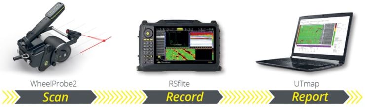
For ultrasonic linear scanning evaluation, a good workflow includes 3 simple steps:
- Scan
- Record
- Report
|
|
|
|
1. Scan the part
The scan step refers to the acoustic parameters that have to be considered for the composite material. For ultrasonic NDT, the A-Scan is the basis of the acquisition and data set. High quality data is vital as the data crossing the gate in the A-scan is directly used to generate the 2D C-scan map. High quality results are required from the linear array probe itself and the recording system.
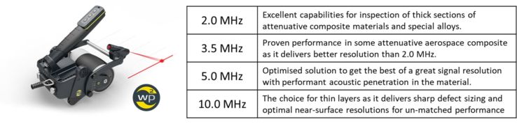
For a good scan, the linear array probe delay line and frequency have to match the composite material thickness and acoustic properties. Innovative design can help to speed-up the scan process whilst providing quality data. The Sonatest WheelProbe2 does both, combining the following features:
- the linear array probe;
- the delay line (water column);
- the coupling layer (patented rubber tire);
- the encoder.
This unique solution delivers similar performance as an immersion system - but it’s portable - and can rapidly scan large surfaces evenly and efficiently.
|
|
|
|
During the scan, another advantageous practice is to include an overlap between C-scan strips to forgive alignment errors. Indeed, these can be overcome during the reporting process by precisely adjusting the position of each strip. However, this can also be optimised by using laser guidance directly mounted on the WheelProbe; this is especially useful when scanning large parts like an aircraft fuselage.
2. Record the information
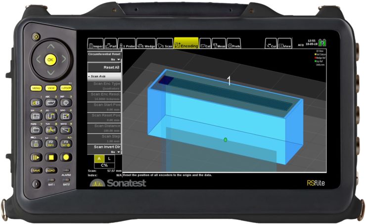
When recording inspection data, the acquisition instrument has to match the material properties, and its user interface must be optimised to suit the needs of the technician. In the composite industry, the ultrasonic linear scanning technology is key. A device that is purely designed to manage L-scan, like the Sonatest RSflite, combines both ultrasonic performance with simplicity of operation. Moreover, the technician expertise and training time can be reduced as most of the Phased Array concepts (like beam steering) are not applicable to L-scan. This also greatly reduces the calibration process.
|
|
|
|
3. Report
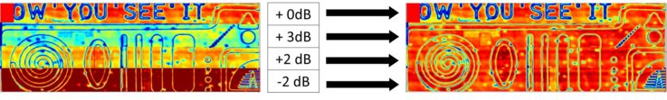
The report must be clear, concise and visual. For ultrasonic NDT of composite materials, a C-scan map is the best way to achieve this. The objective in the C-scan analysis step is to assemble the scan stripes from different sections and create a meaningful image of the total part for analysis and reporting.
When reviewing a C-scan map, some strips of data may need to be precisely re-gated, boosted (increased gain) or re-aligned to match the part geometry. Taking into account the number of strips a large part can generate, a software solution like the Sonatest UTmap helps the user to facilitate this last but important reporting step. Other features like automatic defect measurement tools also help to improve defect sizing precision in a reliable and repeatable manner.
|
|
|
|
In conclusion, the combination of the three steps detailed above create the entire inspection process from acquisition through to submission of the final report. The optimised workflow ensures improved high quality and production output.