
TFMi™ Inspection for monitoring "Blind" Holes
Blind hole inspection is an excellent fit for TFMi™. It really enables a full comprehensive profile view of the internal geometry of a part.
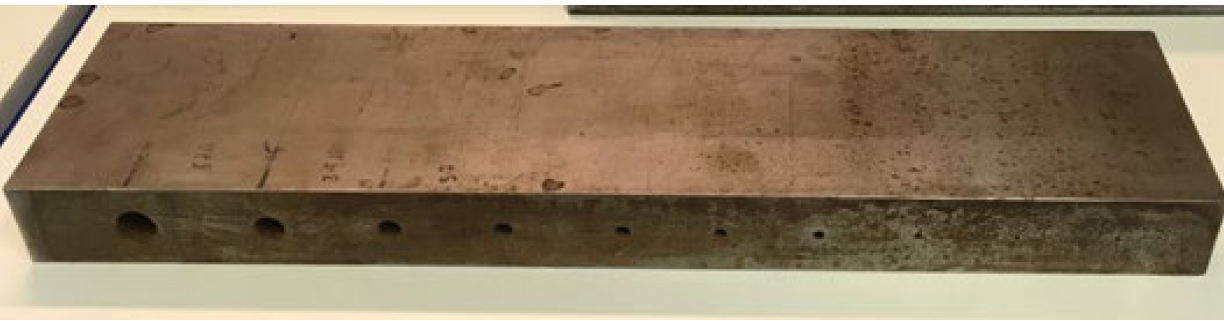
It is sometimes necessary to drill holes with very large depth-to-diameter ratios. A common approach is gun drilling, whereby a cutter is used at the end of a long rotating tool. Ensuring the alignment and consistent diameter of long holes represents an inspection challenge. The TFMi™ feature of the Veo3 provides a useful option when the hole is parallel to nearby surfaces.
Using the TFMi™ NDT technique in the Veo3, with the Intermode set to “Keep Max.” shows the reflected signal from the top surface (LL mode) and the bottom surface (LLLL mode) correctly positioned on screen. A simple gate can be used to measure the gap between them.
TFMi™ Inspection
With the instrument set to a single propagation mode TFM scan only one of the surfaces can be imaged at one time.
Setting the instrument to TFMi™ mode allows us to use up to 4 propagation modes at once. Using the “Keep Max” viewing mode we can see the un-altered results from each mode overlayed on top of each other.
In this inspection we utilised LL and LLLL modes to show the top and bottom reflections from the blind holes. This requires the thickness of the part to be known. For the block used in this study we used a thickness of 50.mm. (See figure 1)
|
|
|
|
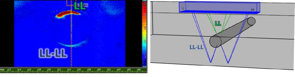
Note when inspecting the larger holes the bottom signal is weaker, this is because the hole is nearly 75% of the size of the probe aperture, this blocks some of the signal to and from the back wall. With the correct gate positioning, avoiding the diffraction signals we can still get an accurate measurement of hole size.
|
|
|
|

Results:
|
|
|
|
|
|


|
|
|
|
|
|


|
|
|
|
|
|


|
|
|
|
|
|


|
|
|
|
|
|


Conclusion
Blind hole inspection is an excellent fit for TFMi™. It really enables a full comprehensive profile view of the internal geometry of a part. The benefit of displaying many propagation modes at the same time has improved complex geometry assessment just as it has been demonstrated in this app note.
There are other similar potential geometry challenges like this where keep max TFMi™ imaging could improve on current inspection methods. Indeed, other propagation modes e.g. LLL or any other shear modes could be utilised with TFMi™ keep-max processing, so additional planar or volumetric features could be added in TFMi™ view.
Recommended Tool Package:
|
Category |
Part # |
Description |
|
Product |
Veo3 16:128 BNC or LEMO TFM |
Veo3 16:128PR/2UT:PR BNC or LEMO TFM |
|
Product Option |
SW-VEO3 LIVE TFM |
The Live TFM option also enables all TFMiTM menus and options. |
|
Probe |
X3A-003 or D5A-001 |
X3A-5M64E-0.6x10-SQX2.5 (Better results with longer probes) |
|
Direct Contact Inspection |
FT1 Tape 100mm |
Polyester tape made for direct contact inspection; it protects the test piece surface and the probe face. |