Inspection of a Welded T-joint
The most common defects in T-joint welds are cracks, lack of fusion and lamellar tearing all of which can be inspected with conventional ultrasonic methods.
The ABC’s of a T-joint
A T-joint consists of two plates welded at 90° to each other in the form of a 'T'. Commonly used in the structural industry, T-joints generally use fillet or groove type welds on each side of the vertical plate, these welds can be ‘part’ or ‘full’ penetration welds, each presenting their own challenges.
Due to the complex geometry of the part, in an A-Scan only view, signals can be difficult to interpret. small inaccuracies in probe positioning or the angle of reflection may place a signal as a defect in the weld when in fact it is it is a reflection from the internal wall. situations like this can lead to false calls and unnecessary repairs.
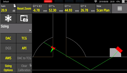
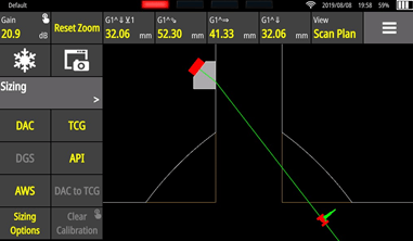
By utilizing the WAVE's unique scan plan and live ray tracing ability, the inspector is able to see exactly where a signal is positioned and give the inspector greater confidence in their result. the ability to screenshot the scan plan also enables more detailed reporting, giving clear and precise images of where any defect indication is positioned within the weld area.
This unique feature makes Wave an ideal instrument for T-joint inspection
Typical Defects in T-joints
The most common defects in T-joint welds are cracks, lack of fusion and lamellar tearing all of which can be inspected with conventional ultrasonic methods.
Lack of fusion or Penetration
A lack of fusion occurs when the base metal is not melted during welding resulting in a lack of cohesion. For T-joints, lack of fusion is commonly seen in between the plates and therefore the optimal way to detect such defects is utilising a straight beam configuration on the lower flange of the joint. However, this may not be accessible.
|
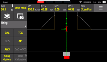
Scan Plan – Lack of fusion or penetration |
|
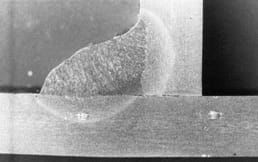
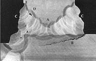
Microstructure – Lack of fusion or penetration |
Lamellar tearing occurs when there is a weld contraction combined with low ductility of the base metal. This generates a very high stress concentration, located in the base metal, outside or close of the heat affected zone (HAZ). The tearing is generally parallel to the weld fusion surface.
Unfortunately, T-joint as well as corner joint are affected by this type of defect due to high through-thickness strain.
Lamellar tearing can be easily detected by an inspection from the lateral web of the joint because of its predictable orientation.
|
Scan Plan |
|
Microstructure. KOU, Sindo (2003) Welding Metallurgy. New Jersey, USA: John Wiley & Sons |
Cracks
A crack is a combination of metallurgical and mechanical failures. It usually occurs due to pre-existing stresses, generally caused by thermal expansion, solidification, shrinkage or both. For example, aluminium alloys have a high thermal expansion coefficient and solidification shrinkage.
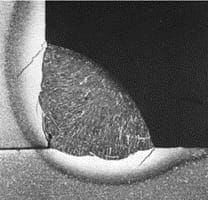
On a T-Joint with fillet welds on both sides, the second side is more restrained mechanically. Hence, this side will be more susceptible to cracks, as seen in the figure below.
It is difficult to correctly predict the orientation of cracks, as they can be detected from many inspection angles based on the sample geometrical aspects.
|
Scan Plan |
|
Microstructure. KOU, Sindo (2003) Welding Metallurgy. New Jersey, USA: John Wiley & Sons |
CODES & STANDARDS
Welded structures have to meet applicable codes and standards related to their intended use. The welding process, inspection technique and acceptance criteria vary.
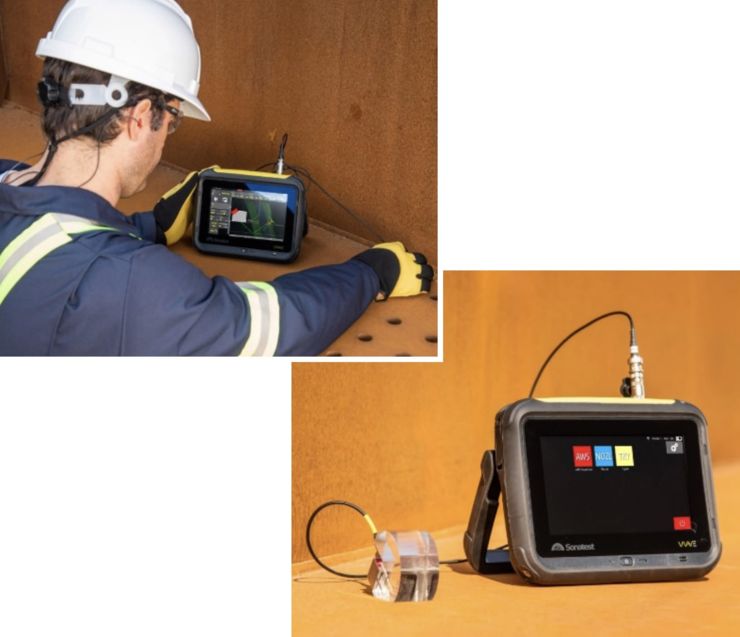
For structural welding inspection to the American Welding Standard (AWS), the most important measurements are the indication level, reference level, attenuation factor and the indication rating. The Sonatest Wave has a built-in single touch application for inspecting to AWS requirements. Hence, after an AWS calibration, the user is able to select the AWS measurements associated with the corresponding gate. In addition, the indication rating is automatically calculated, which improves the reporting efficiency.
|
Sonatest WAVE instrument with pre-defined AWS & TKY set ups
WAVE Interactive Scan plan for T-Joint inspection |
For further information or support, please contact the Sonatest Applications Team: applications@sonatest.com
