Inspection of Composite Materials
Composites have become a dominant material in the Aerospace, Automotive and Energy sectors as well as many more areas where they are providing innovative solutions over the conventional materials used in the past. Here we discuss the ultrasonic inspection methods for composite materials.
Composites have become a dominant material in the Aerospace, Automotive and Energy sectors as well as many more areas where they are providing innovative solutions over the conventional materials used in the past. Amongst a number of advantages composites provide high strength with low weight and corrosion resistance. However, quality assessment of composite parts is challenging.
Adopting recognised ultrasonic techniques to perform NDT inspection of composite components can provide reliable and repeatable results for both in-line and maintenance examination.
A phased array linear scan (0-degree) inspection is highly recommended. Composites are anisotropic, meaning that they have different properties when measured in different axis, thus the velocity of transverse waves varies with the beam angle, making angular scans a poor method of inspection.
Conventional through transmission techniques are also useful tools for composite inspections on sandwich structures and thin components.

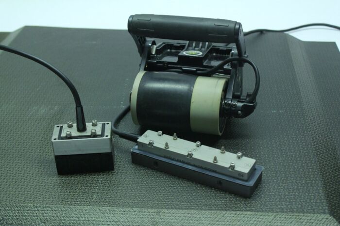
Phased Array Probes used for Composite inspection
Composite Defects may originate from mishandling or abuse but can also be unintentionally created at the time of production. Lack of detection may lead to a much shorter part lifespan and possible failure in service.
Fabrication Defects:
- Insertion of unknown material between plies
- Poor bonding (lack of adhesive)
- Layers overlapping
- Porosities
- De-laminations (caused by human manipulation or machining)
Mechanical Damage Defects:
- Stress, Fatigue and Shearing
- Impacts
- Heat
- Abrasion
- Chemical Reaction
Phased Array L-scans can be used to map large areas of a surface quickly, these can be viewed in C-scans and can display the information according to the time=of-flight or the amplitude of the signal. For composite inspection, both sets of information are important because they highlight defect zones differently.
Amplitude base C-scan gate positioning would often monitor the back-wall echo of the part. This information would be very sensitive to coupling variation, disbonding, porosity or anything that would affect signal strength.
Time of flight C-scan gate positioning would be position in between the backwall echo and the Emission echo. This view is generally less sensitive than the previous one however it keeps the Depth information of the flaw.

C-Scan Amplitude image

C-Scan Time-of-flight image
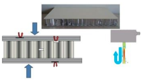
Through Transmission Inspection is an approach used for the inspection of honeycomb structures, Such structures can be inspected with two set of dry probes apart from each other. Such approach it able to detect disbonding of the panel from the core material.

Through transmission technique

Honeycomb structure defect examples
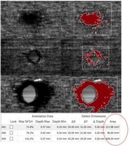
Sizing of defects found in composite materials can be challenging, to aid in this task Sonatest developed an automated indication sizing tool within the UTmap software, which allows the inspector to quickly find and size indications of all shapes. UTmap defective zone algorithms based on amplitude or time-of-flight signals use fully editable detection criteria. The algorithm gives visual feedback of the defective area while sending dimensional information about the defect such as depth, width, length, global area etc.

UTmap software highlighting defect dimensions, providing visual sizing and full dimensional data
For further information or support, please contact the Sonatest Applications Team:
