Identifying the Recording Speed Limitations of Your Ultrasonic Instrument
![]() 19th May 2021
19th May 2021
Francois Lachance
Sonatest

The recording speed of an ultrasonic instrument remains an important parameter to consider before you make your purchase. An instrument with low recording speed will impact the productivity of your team and may also cause missed frames.
Finding the recording speed performance of an ultrasonic instrument
Unfortunately, the recording speed performance of an ultrasonic instrument is rarely, if ever, provided in its specification sheet. The main reason is that the recording speed depends greatly on your inspection configuration. In addition, there is no standardised approach or consensus between instrument manufacturers to add the recording speed to a product’s description.
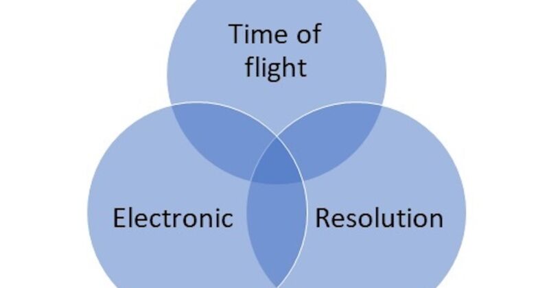
Physically, the recording speed limitation of a phased array instrument comes from three distinct limitations. These limitations are represented in Figure 1. Each of them could be subdivided into a list with the instrument’s attributes or characteristics.

The electronic limitation is generated by the electronic architecture and design choices. Product characteristics, such as maximum PRF (Pulsing Receiving Frequency) and data buffering, would play a major role for this limitation. Indeed, high PRF performance can only be reached with the right electronic components. The data buffering limitation is caused by the slowest electronic component of the instrument. An instrument with the proper architecture, such as the veo3, mitigates this limitation furthermore.
The time of flight limitation is generated by the required time for the sound to travel to the part that needs to be inspected. This limitation is related to the physics of the technique and could be computed by this basic dynamic formula:
Time (s)= Thickness (mm)/Velocity (mm/s)
In other words, this limitation means that the recording speed cannot be higher than the time required by the sound to do a round trip of the part. This limitation is one of the main bottlenecks for inspections of thick parts and angle beam inspection. It is important to note that the time spent in the medium (wedge/water) must be factored into the equation and is often the cause of the bottleneck. For example, the water velocity is four times slower than steel, which means that a 10mm water column could add up to an equivalent of 40mm of steel in your total sound path.
Finally, the resolution limitation is generated by the configuration setup. The higher the resolution, the slower the scan records. Some parameters, such as the angle resolution, directly affect the time of flight by generating more beam. Others, such as the range or length, would have a greater impact on data buffering.
How the Veo3 tackles recording speed problems
The Veo3’s electronic and software is powered by a unique architecture with a superior data throughput and unsurpassed computational capacity that delivers fast and accurate results in the most demanding conditions. The Veo3’s performance levels are so good, that for a PAUT scan configuration, it is virtually impossible to be impacted by the electronic bottlenecks of the instrument. This means that if your recording speed is slow, it is always related to the time of flight of the sound path, not the instrument’s performance.